N8MR
Quest for DXCC on 160 Meters
The minimalist's approach
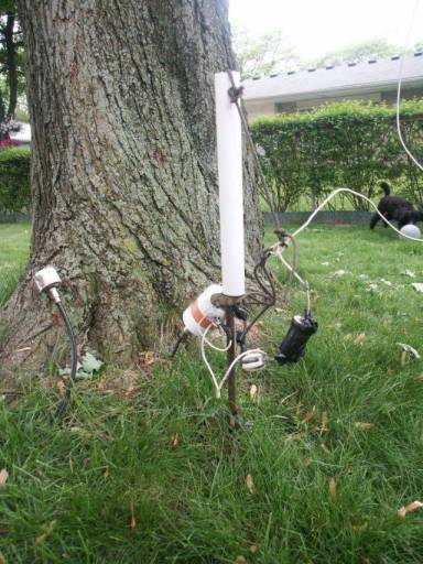
The "New and Improved" Feedpoint
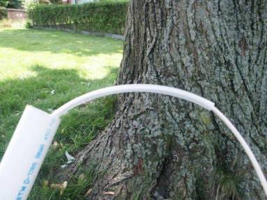
Old feed point.
In early August of 2005, the SWR on the inverted L had suddenly gotten
suspiciously high. The feedline and antenna seemed to be in good shape. The
last suspect was the inline capacitor. In late 2004, I had replaced the two
parallel mica capacitors with a single doorknob cap, and it had been causing
the SWR to drift with temperature. Could it be that the cap was defective
and finally gave up the ghost?
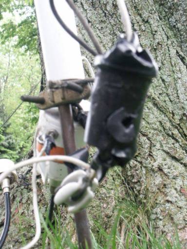
Hole in the bottom.
Upon inspection of the inline cap (which had been housed in a 35mm film canister)
it became apparent that some four-legged creature had used the canister as a
chew toy. A hole in the bottom/side allowed moisture to enter the formerly sealed
canister. Also, the doorknob capacitor was slightly crushed. A new feedpoint
arrangement was needed. The new feed point had to be made so that none of the
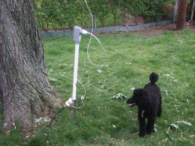
four-legged suspects could ever reach the capacitor or the radiating element. It
also had to be made so that the radiating element could swing around in the wind
without causing damage to the wire.
After two trips to the local hardware store (one trip is never enough), all of
the necessary materials were gathered:
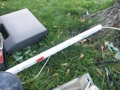
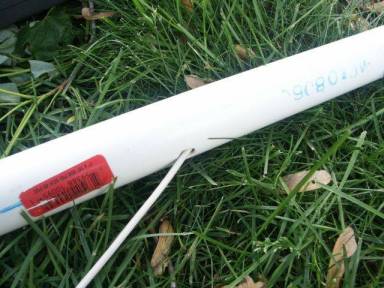
1- a three-foot length of 1-inch diameter PVC pipe
2- a plastic conduit box with a 1-inch opening at the bottom
3- a two-foot length of flexible plastic tubing, with an inner diameter
wide enough to snugly fit an insulated 12AWG wire through
4- a two-foot length of larger plastic tubing with an inner diameter
just wide enough for a snug fit over the top of the ground rod
5- a miscellaneous plastic reducer; one end wide enough for a snug fit
inside the upper hole of the conduit box, the reduced end small enough
to provide a snug fit for the flexible plastic tubing
6- a wide plastic washer, just big enough to cover the bottom hole
inside the conduit box.
The two-foot length of plastic tubing was put over the top of the ground rod
and pushed down to the upper ground clamp. This covers the rough edges on
the top of the ground rod. It also provides two other functions, mentioned later.
The three-foot section of PVC pipe was stood up on top of the upper ground
clamp. A mark was placed at a location 1-inch above the top of the plastic
tubing and a hole was drilled at an upward angle at that mark. The size of the
hole was just large enough for a snug fit of the smaller-diameter plastic tubing.
The four-foot length of smaller diameter plastic tubing was cut in half, one
piece was fit over a new length of 12AWG wire. That wire was then placed
within the 1" PVC pipe so that one end was sticking out the angled hole,
while the other stuck out the opposite open end.
The smaller-diameter plastic tubing will then be a strain relief of sorts for
the end of the wire exiting the drilled hole. It will also, with the air of
the larger plastic tube on the ground rod, protect the internal wire from
abrasions, should the assembly swing around in the wind. The larger diameter
tubing should also, theoretically, allow the PVC pipe to swing around easier
on the ground rod.
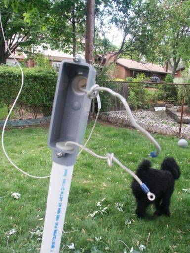
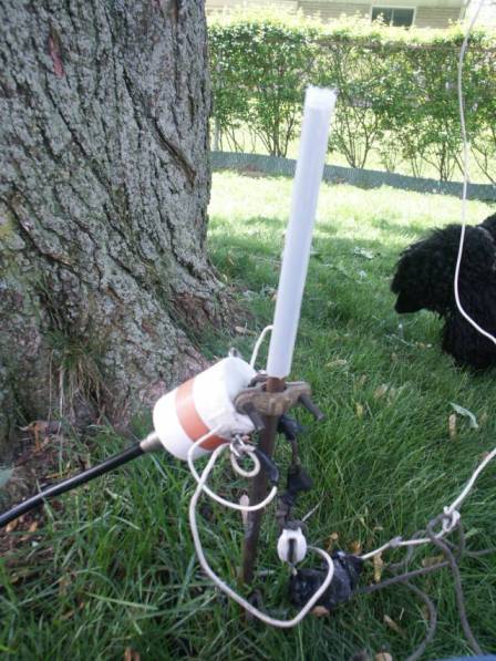
The PVC pipe was placed over the top of the ground rod, so that the drilled
hole was near the ground rod. The conduit box was fit onto the top of the PVC
pile. The wire was threaded through the bottom hole, the plastic washer placed
over the wire and a loose knot tied in the wire, as a crude strain relief.
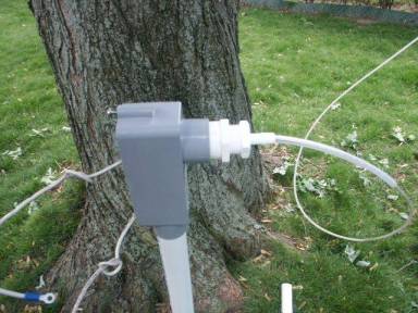
The reducer was fit snug into the upper hole of the conduit box. The second
half of the smaller diameter plastic tubing was fit over the radiating element
wire, then into the hole of the reducer. This allowed for a tighter fit of the
radiating element wire, as well as a semi-flexible strain relief. A loose
knot was tied in the radiating element wire, just inside the conduit box,
as another crude strain relief.
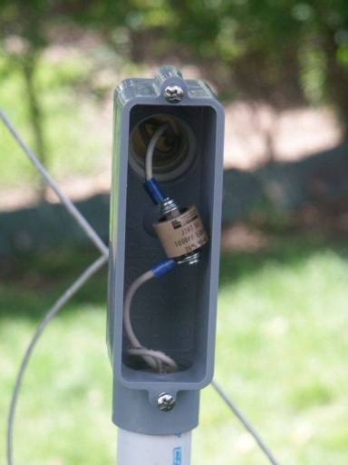
Two eyelet terminals were soldered to the ends of the wires inside the conduit
box. A new doorknob cap was then bolted to the eyelets. The weather-proof
cover of the conduit box was secured.
The wire sticking out the angled drilled hole, near the bottom of the PVC pipe,
was soldered to the feedpoint wire at the ceramic egg insulator, as it had been
previously. The four-legged creatures have not shown any signs of interest in
these components, so leaving them as-is shouldn't be a problem.
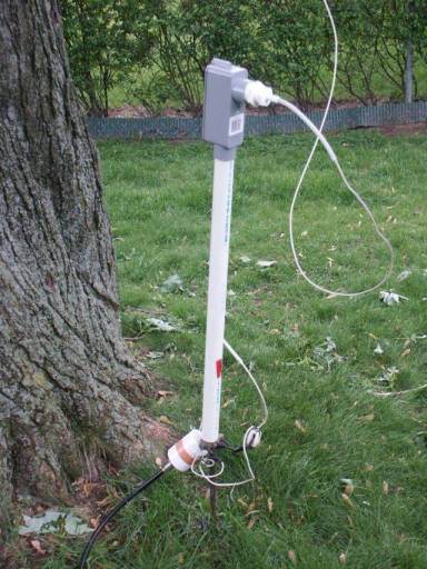
Voila!
The "new and improved" feedpoint. It allows the radiating element to swing
around in the wind, while keeping it and the inline capacitor well out of
harm's way.
Side notes:
1.) In late November 2005, the SWR curve of the antenna was once again shifting
with the outside temperature. The doorknob capacitor was replaced with two
parallel 500pF mica capacitors, and the SWR-shifting problem went away.
2.) While the capacitor was being replaced, the inside of the conduit box
showed no signs of insect squatters.
Return to N8MR
Inverted L Antenna
Receiving Loop Antenna
How am I doing with this setup?
N8MR tracks all comments and questions for this page.